
Introduction
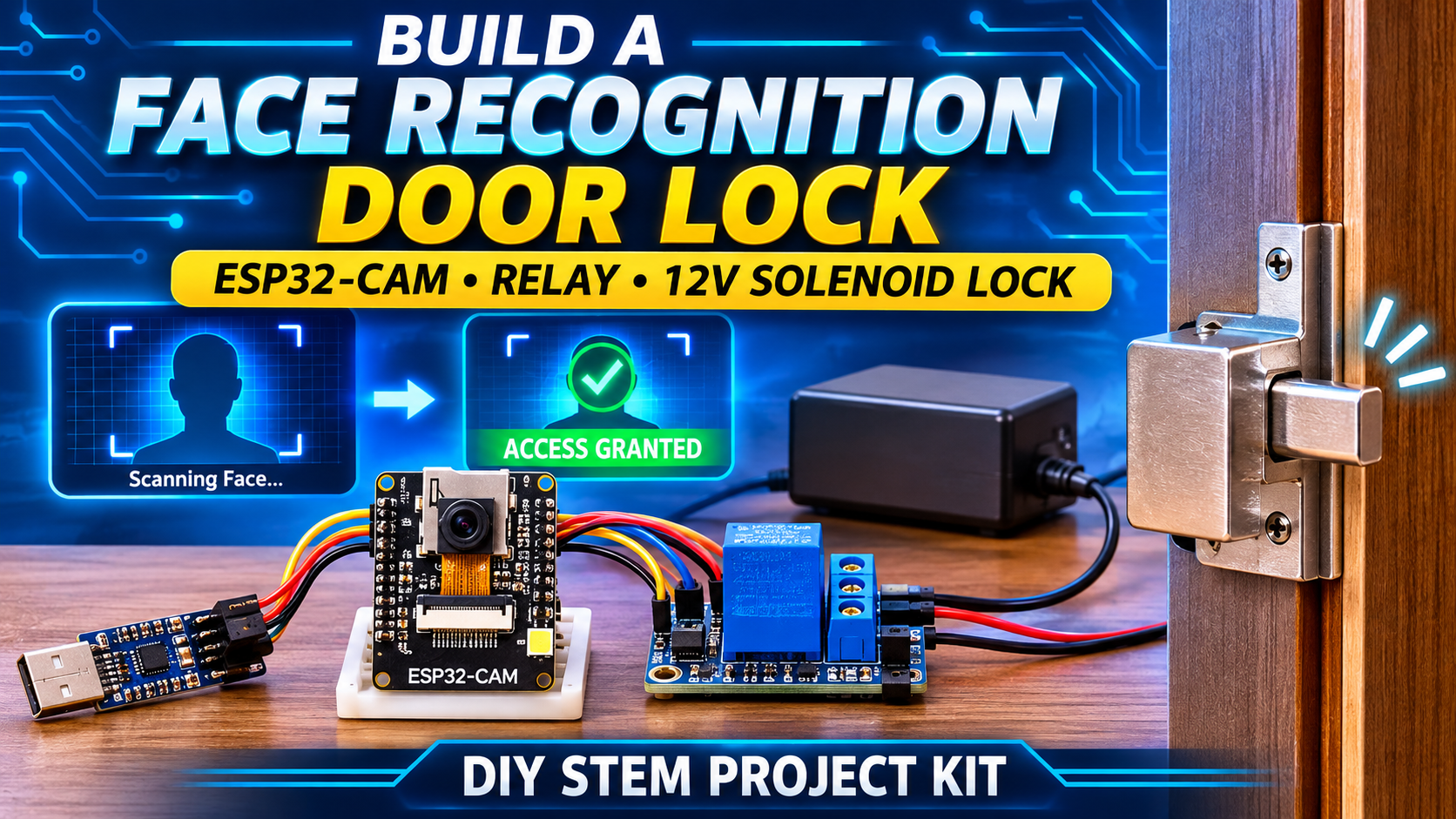
What if your door could recognise your face and unlock itself automatically — with zero keys, zero cards, and zero PIN codes? That's exactly what this project delivers. Using the incredibly powerful ESP32-CAM module, you can build a complete AI-powered face recognition door lock system that runs entirely on a single ₹850 board.
The ESP32-CAM has a built-in OV2640 camera, onboard Wi-Fi, and enough processing power to run real-time face detection and recognition using Espressif's own AI frameworks — all locally on the chip, with no cloud dependency required. When an enrolled face is recognised, it triggers a relay module that activates a 12V solenoid door lock or a servo motor latch to unlock the door.
This is a perfect project for college final year projects, home security, office access control, smart hostel rooms, and IoT AI demonstrations. All components are available at Anil Electronic Store, Ahmedabad.
What You'll Build
- A live camera stream accessible from any browser on your Wi-Fi network
- Real-time face detection and recognition running directly on the ESP32-CAM
- Enrol multiple authorised faces through a web interface — no code changes needed
- Recognised face → relay triggers → door unlocks for 5 seconds → auto re-locks
- Unknown face → relay stays off → door remains locked
- Green LED for access granted, red LED for access denied
- Optional: buzzer beep on successful recognition
- Total build time: ~2 hours
How It Works
The system works in three clear stages:
- Camera streaming & face detection: The ESP32-CAM continuously captures frames from its OV2640 camera and runs Espressif's onboard face detection algorithm (MTMN model) to locate faces in the frame in real time.
- Face recognition & matching: When a face is detected, the ESP32 runs face recognition to generate a feature vector and compares it against all enrolled face vectors stored in its flash memory. If the similarity score exceeds the recognition threshold, the face is confirmed as authorised.
- Door unlock & re-lock: On a successful match, GPIO4 of the ESP32-CAM goes HIGH, triggering the relay module. The relay switches the 12V solenoid lock (or servo latch), unlocking the door for 5 seconds before automatically re-locking.
Understanding the ESP32-CAM Module
The AI-Thinker ESP32-CAM is a compact development board built around the Espressif ESP32-S chip. Key specifications relevant to this project:
- Processor: Dual-core 32-bit LX6 at 240MHz — fast enough to run face recognition at ~15 FPS
- Camera: OV2640, up to 2MP (1600×1200), JPEG output
- Memory: 4MB Flash + 4MB PSRAM — the PSRAM is critical for storing face feature vectors
- Wi-Fi: 802.11 b/g/n 2.4GHz — streams live video to any browser
- GPIO: IO4 is used for the relay in this project (also doubles as flash LED)
- No USB port: Requires an external FTDI programmer (FT232RL or CH340G) to upload code
⚠️ Important: The ESP32-CAM does NOT have a built-in USB port. You MUST use an external USB-to-serial (FTDI/CH340) adapter to program it. This is included in the BOM below.
Components Required (BOM)
All components below are in stock at anilestore.com with same-day dispatch before 2 PM. See the kit panel on this page to add everything in one click.
Circuit Connections
CH340G USB-to-TTL Programmer → ESP32-CAM (for uploading code only):
- CH340G VCC → ESP32-CAM 5V
- CH340G GND → ESP32-CAM GND
- CH340G TX → ESP32-CAM UOR (RX)
- CH340G RX → ESP32-CAM UOT (TX)
- GPIO0 → GND (short this ONLY during upload — remove after uploading)
1-Channel Relay Module → ESP32-CAM (for door lock control):
- Relay VCC → ESP32-CAM 5V
- Relay GND → ESP32-CAM GND
- Relay IN (Signal) → ESP32-CAM GPIO4
12V Solenoid / Door Lock → Relay Module:
- Relay COM → 12V Power Supply positive
- Relay NO (Normally Open) → Solenoid Lock positive wire
- Solenoid Lock negative wire → 12V Power Supply GND
If using a servo motor latch instead of solenoid lock — connect servo signal to GPIO2, red to 5V, brown to GND. Skip the relay module for servo-based builds.
Green LED → ESP32-CAM:
- Anode (+) → GPIO2 via 220Ω resistor
- Cathode (–) → GND
Red LED → ESP32-CAM:
- Anode (+) → GPIO13 via 220Ω resistor
- Cathode (–) → GND
Active Buzzer → ESP32-CAM:
- Positive → GPIO12
- Negative → GND
Power:
- Once code is uploaded, power the ESP32-CAM via its 5V pin from a 5V 2A USB adapter or power bank
- The 12V solenoid lock requires a separate 12V power supply — use the 12V 1A adapter from the BOM
- Both GND rails must be connected together (common ground)
Arduino IDE Setup
- Open Arduino IDE → File → Preferences
- Add this URL to Additional Board Manager URLs:
https://dl.espressif.com/dl/package_esp32_index.json - Go to Tools → Board → Board Manager, search esp32 by Espressif Systems, and install version 2.x
- Select board: AI Thinker ESP32-CAM
- Set partition scheme: Huge APP (3MB No OTA/1MB SPIFFS) — this is essential for face recognition to fit in flash
- Set COM port to your CH340G adapter's port
Upload Mode — Step by Step
The ESP32-CAM requires a special upload procedure since it has no onboard USB:
- Connect the CH340G USB-to-TTL adapter to the ESP32-CAM as per the circuit connections above
- Short GPIO0 to GND using a jumper wire — this puts the ESP32-CAM into bootloader (programming) mode
- Connect the CH340G to your laptop via USB
- In Arduino IDE, select the correct COM port and board settings
- Click Upload
- When you see
Connecting....____in the console, press the RESET button on the ESP32-CAM once - Wait for upload to complete (shows
Hash of data verified) - Remove the GPIO0 to GND jumper wire
- Press RESET again — the camera will now start in normal run mode
The Face Recognition Code
The easiest way to run face recognition on the ESP32-CAM is to use the built-in example from the ESP32 Arduino core. This example includes a complete web server, live video streaming, face detection, and face recognition — all in one sketch.
- In Arduino IDE go to: File → Examples → ESP32 → Camera → CameraWebServer
- At the top of the sketch, find the camera model definitions and uncomment this line:
#define CAMERA_MODEL_AI_THINKER - Comment out all other
#define CAMERA_MODEL_...lines - Fill in your Wi-Fi credentials:
const char* ssid = "YOUR_WIFI_SSID";
const char* password = "YOUR_WIFI_PASSWORD"; - Upload the sketch using the upload procedure above
Adding the Door Lock Relay Control
After uploading the base CameraWebServer example, you need to add relay, LED, and buzzer control. Add the following code to the sketch:
// ESP32-CAM Face Recognition Door Lock
// Anil Electronic Store – anilestore.com
// Add this code to the CameraWebServer example

#define RELAY_PIN   4   // GPIO4 — relay signal
#define GREEN_LED   2   // GPIO2 — access granted LED
#define RED_LED     13  // GPIO13 — access denied LED
#define BUZZER_PIN  12  // GPIO12 — buzzer

long prevMillis = 0;
int unlockDuration = 5000; // Door stays unlocked for 5 seconds
bool doorUnlocked = false;

// Call this in setup() after camera init:
void lockSetup() {
  pinMode(RELAY_PIN,  OUTPUT);
  pinMode(GREEN_LED,  OUTPUT);
  pinMode(RED_LED,    OUTPUT);
  pinMode(BUZZER_PIN, OUTPUT);

  digitalWrite(RELAY_PIN,  LOW);  // Door locked on start
  digitalWrite(GREEN_LED,  LOW);
  digitalWrite(RED_LED,    HIGH); // Red LED ON = locked state
  digitalWrite(BUZZER_PIN, LOW);
}

// Call this when face is RECOGNISED:
void unlockDoor() {
  Serial.println("ACCESS GRANTED – Face recognised!");
  digitalWrite(RELAY_PIN,  HIGH); // Activate relay → unlock door
  digitalWrite(GREEN_LED,  HIGH); // Green LED ON
  digitalWrite(RED_LED,    LOW);  // Red LED OFF
  digitalWrite(BUZZER_PIN, HIGH); // Beep
  delay(150);
  digitalWrite(BUZZER_PIN, LOW);
  delay(50);
  digitalWrite(BUZZER_PIN, HIGH);
  delay(150);
  digitalWrite(BUZZER_PIN, LOW);

  prevMillis = millis();
  doorUnlocked = true;
}

// Call this when face is NOT recognised:
void denyAccess() {
  Serial.println("ACCESS DENIED – Unknown face.");
  digitalWrite(RED_LED,    HIGH);
  digitalWrite(GREEN_LED,  LOW);
  digitalWrite(BUZZER_PIN, HIGH);
  delay(600);
  digitalWrite(BUZZER_PIN, LOW);
}

// Call this in loop():
void checkAutoLock() {
  if (doorUnlocked && (millis() - prevMillis >= unlockDuration)) {
    Serial.println("Auto re-locking door...");
    digitalWrite(RELAY_PIN, LOW);  // Deactivate relay → lock door
    digitalWrite(GREEN_LED, LOW);
    digitalWrite(RED_LED,   HIGH); // Red LED back ON = locked
    doorUnlocked = false;
  }
}
In the main loop() of CameraWebServer, find where the face recognition result is used and call unlockDoor() when the result is positive, denyAccess() when negative, and checkAutoLock() every loop iteration.
Using the Web Interface
Once the ESP32-CAM is running, open the Serial Monitor at 115200 baud. You will see an IP address printed — something like 192.168.1.112. Open this in any browser on the same Wi-Fi network.
The web interface gives you:
- Start Stream — begins the live video feed from the camera
- Face Detection toggle — turns on the face detection bounding boxes
- Face Recognition toggle — enables the recognition engine
- Enroll Face button — saves the currently detected face to memory. Stand in front of the camera and click this button 5–10 times from slightly different angles for best accuracy
- Resolution, Quality, Brightness sliders — adjust camera settings for your lighting conditions
Enrolled faces are stored in the ESP32-CAM's PSRAM and persist across power cycles (stored to flash). You can enrol multiple faces — each is assigned a subject number (Subject 0, Subject 1, etc.).
Optimising Face Recognition Accuracy
- Lighting: Ensure the face is well-lit and evenly illuminated. Avoid strong backlighting from windows behind the person.
- Distance: Optimal recognition range is 30–80 cm from the camera. Too close or too far reduces accuracy.
- Enrolment angles: When enrolling, slightly turn your head left, right, up, and down across multiple captures — this improves recognition across angles.
- Threshold tuning: In the web interface, reduce the recognition threshold slightly if you're getting too many false rejections with the same face.
- Resolution: Set to QVGA (320×240) for fastest face recognition. Higher resolutions slow down the AI inference significantly.
- Re-enrol in target environment: Always enrol faces in the same lighting conditions and location where the lock will be installed.
Step-by-Step Assembly
- Prepare the ESP32-CAM: Insert the OV2640 camera ribbon cable firmly into the ESP32-CAM connector — it should click in. This is a fragile connector; handle it gently.
- Upload the code: Wire the CH340G USB adapter to the ESP32-CAM, short GPIO0 to GND, and upload the modified CameraWebServer sketch as described above.
- Wire the relay module: Connect the relay IN pin to GPIO4 of the ESP32-CAM. VCC to 5V, GND to GND.
- Wire the LEDs and buzzer: Connect green LED (via 220Ω) to GPIO2, red LED (via 220Ω) to GPIO13, buzzer to GPIO12.
- Wire the door lock: Connect the relay's COM and NO terminals in series with the 12V power supply and the solenoid lock. Keep 12V wiring separate from the ESP32-CAM's 5V wiring — only the GND rails should be shared.
- Mount the camera: Fix the ESP32-CAM module at door height (roughly chest height, 100–120 cm from floor) pointing straight ahead. The camera should have a clear view of faces approaching the door. Use a small enclosure box or 3D-printed mount.
- Power up and enrol faces: Power the system, navigate to the ESP32-CAM's IP in your browser, enable face detection and recognition, and enrol authorised faces using the Enroll Face button.
- Test the lock: Walk in front of the camera. For an enrolled face — green LED, two beeps, relay clicks, door unlocks. For unknown faces — red LED, long beep, door stays locked.
Troubleshooting Tips
- Camera not initialised / brown-out detected: The ESP32-CAM needs a stable 5V supply with at least 500mA current. USB adapters that share current with other devices often brown out the ESP32-CAM. Use a dedicated 5V 2A adapter.
- Upload fails / no COM port detected: Ensure GPIO0 is shorted to GND before uploading. Install CH340G driver on Windows. Try pressing RESET when the console shows
Connecting.... - Face not being recognised (always denied): Re-enrol the face in the same lighting conditions. Try reducing the recognition threshold in the web interface. Ensure PSRAM is enabled in Tools menu.
- Relay clicks but solenoid doesn't open: Check that the 12V power supply is connected and powering the solenoid. Verify COM and NO terminals are used (not NC). Ensure common GND between ESP32-CAM and 12V supply.
- Live stream choppy or not loading: Reduce resolution to QVGA in the web interface. Ensure the ESP32-CAM is close to the Wi-Fi router. Avoid interference from other 2.4GHz devices.
- Board not found in Arduino IDE: Ensure you installed the ESP32 board package by Espressif. Select AI Thinker ESP32-CAM specifically — not a generic ESP32 board.
Upgrading to Servo-Based Latch
If you don't have a solenoid lock, you can use the TowerPro MG995 servo motor as a mechanical latch driver instead — this is a great option for prototyping and science fairs:
- Connect the MG995 servo signal wire to GPIO2 of the ESP32-CAM
- VCC to 5V, GND to GND (use an external 5V supply for the servo — ESP32-CAM's 5V pin may not supply enough current for MG995)
- In the code, include
<ESP32Servo.h>and rotate the servo to 90° on recognition and back to 0° after 5 seconds - No relay module needed for this approach
Upgrades & Next Steps
- Add a pushbutton inside the door for manual override unlock — always needed as a failsafe
- Add a Telegram bot notification — receive a photo of every person who attempts access, with access granted/denied status
- Add a DS3231 RTC module + SD card to log all access attempts with timestamps
- Use MQTT and Home Assistant to monitor and control the lock remotely from your phone
- Add a keypad as a PIN backup for when face recognition fails in poor lighting
- Use an OLED display to show "Welcome, Authorised User!" or "Access Denied" messages at the door
- Combine with the RFID Door Lock (our previous blog) for dual-factor authentication — both RFID card AND face recognition required to unlock
Real-World Applications
- 🏠 Smart home door lock — unlock your front door with your face
- 🏫 College lab / server room access — only enrolled staff can enter
- 🏢 Office attendance + access control — combined face recognition and check-in system
- 🏨 Hostel room lock — no keys needed, face is the key
- 🔬 Final year BE/BTech project — impressive, technically sound, real-world applicable
- 🚗 Vehicle security — face recognition ignition lock for cars or bikes
Why Buy from Anil Electronic Store?
- ✅ Genuine AI-Thinker ESP32-CAM modules with OV2640 camera — tested and verified
- ✅ CH340G USB adapters for hassle-free programming — driver included in product listing
- 🚚 Same-day dispatch for orders placed before 2 PM from Ahmedabad
- 🧾 Official GST invoice — ideal for college project budget reimbursements
- 📲 Free WhatsApp engineer support — we help with upload errors, wiring issues, and code
- 📦 Delivery across 19,000+ PIN codes all over India
Conclusion
The ESP32-CAM Face Recognition Door Lock is one of the most technically impressive and genuinely practical projects in the Arduino and IoT ecosystem. It combines edge AI, computer vision, Wi-Fi connectivity, relay control, and hardware security — all running on a single ₹850 module that fits in the palm of your hand.
Whether you're building a smart home security upgrade, a college final year project, or a commercial access control prototype — this system delivers real face recognition results with an easy-to-use web interface and no cloud dependency.
All components in the BOM are 100% genuine, tested, and in stock at Anil Electronic Store. Order before 2 PM for same-day dispatch across 19,000+ PIN codes in India. Your face is the key — build it today! 🤖🔐⚡